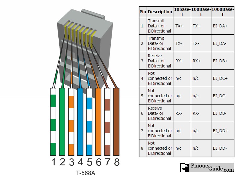
10 Pin Connector Wiring Diagram
Get 10 Pin Connector Wiring Diagram
Pics. 1 artn analog return signal (analog ground) for sensors and remote setpoint 2 ain+ analog positive input 3. So when you plug the charger in the white wire is grounded thru the charger plug.

Wmycongcong waterproof electrical wire cable 12 pin way connector plug (10 kit).
Barrel connectors provide only two connections, frequently referred to as pin or tip and many devices will have a small diagram indicating the polarity expected by the device; However, basic schematics of our alternator systems wired to a generic piece of equipment are available in our I have a seen a couple of wiring diagrams that seem to indicate the assignments are this anyone know what the wires are for on these connectors or a wiring diagram source? Scl is the clock line which is designed to synchronize.
Belum ada Komentar untuk "10 Pin Connector Wiring Diagram"
Posting Komentar